Chasing the Speed of Light

Measuring the speed of light on my workbench

Many moons ago I was reading about how the speed of light was discovered. Along the way I realized that I could set up a test at home and get pretty close to the known value. Since speed is just distance divided by time it's pretty easy to grasp. The issue is accurately measuring something that's traveling at 299,792,458 meters per second. Since I spend quite a bit of time at the SPAC Optical Lab my first thought was to use a laser, beam splitter and a couple of front coated mirrors with photo sensors. Detecting the start time and end time of the same laser pulse and knowing the distance it traveled would would give me the speed. The only parts that I had available were an oscilloscope and the front coated mirrors.

While looking for a beam splitter and light sensors I came across a Speed of Light Apparatus from Industrial Fiber Optics. This was available as a kit or assembled and it had the advantage of using a 20 meter fiber optic cable instead of trying to align a laser and mirrors. I bought the kit and spent about two hours assembling it checking each resister, diode and magnifying each solder joint for inspection. It worked as advertised as soon as it was powered up.

Calibrating the device

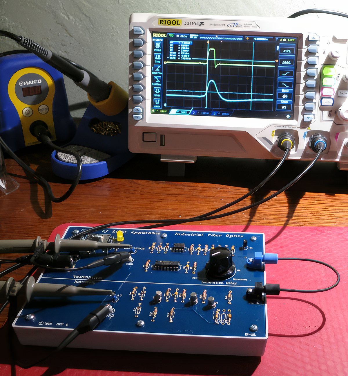
After assembling the kit I polished the fiber ends, and I use 'polishing' very loosely here since I was polishing with the supplied very fine grit sandpaper. There are two fiber pieces included, one short piece used for zero calibration and the 20 meter piece to perform the actual speed test. In the calibration photo above the short piece is used with the delay knob to align the starting and ending signal. The time that light travels in the short piece is under a nanosecond (ns) and is, effectively, zero. The calibration adjustment on the circuit board allows the return signal to align with the transmitting signal. This should also compensate for the 5% tolerances on some of the parts.

When measuring the speed of light through anything other than a vacuum the refractive index needs to be taken into account. The plastic fiber supplied has a refractive index of 1.5 which we'll multiply against the fiber length later.

Now that we have the test platform zeroed it's time to swap the short fiber for the 20 meter fiber.
Testing with a 20 meter fiber optic cable

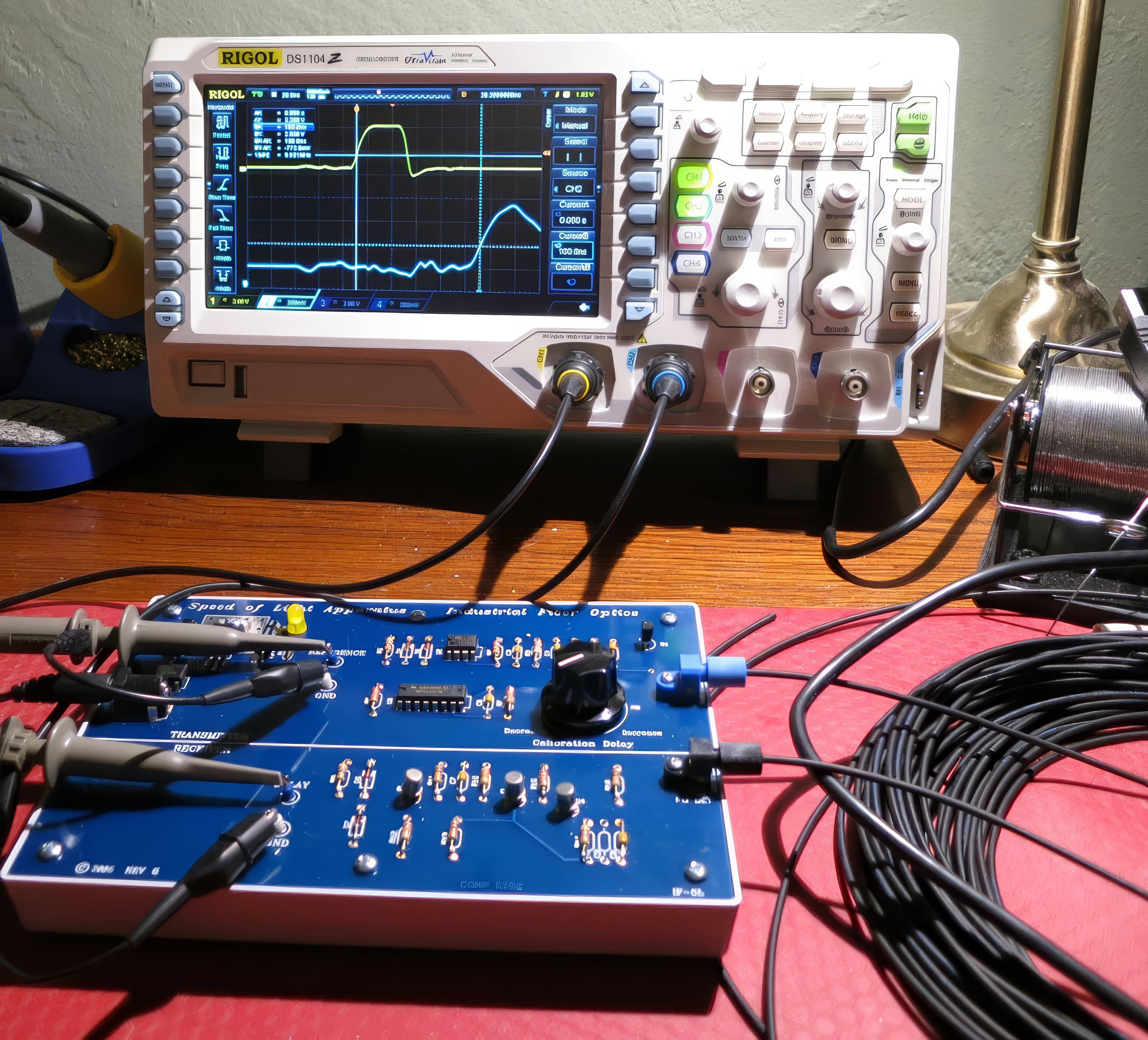
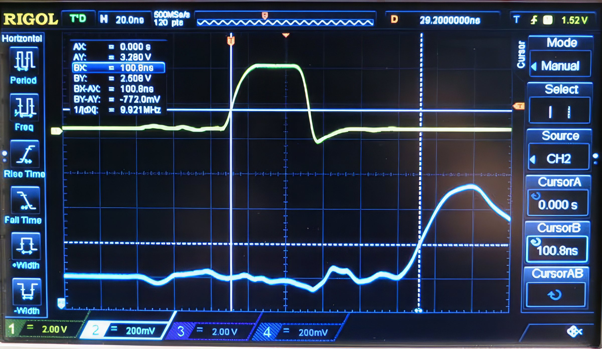
The photo above shows the 20 meter fiber and the vertical cursors (lines) on the oscilloscope. The fibers must be inserted complete in the cinching holders or the values change. Below is a close-up of the results. On the right hand side notice that Cursor-A is on zero and Cursor-B is on 100.8ns. My oscilloscope runs at 50MHz on each channel when two channels are active. The kit recommends a 20MHz or faster oscilloscope.

20 meter test

Here is the oscilloscope display with the cursers showing where they measured the exiting and return light after 20 meters of travel. The shift to the right is the time difference. The speed of light taking into account the refractive index of the fiber.

Speed Test Results

In a perfect world my test would have come in at 100.1ns which would be 100%. This test came in at better than 99%. My tests have varied between 100.8ns and 101.2ns. There are many variables here that affect the outcome: Is the cable exactly 20m? Is the refractive index exactly the published 1.5? Is the calibration adjustment exactly on zero? What is the resolution of the oscilloscope? Did I measure the vertical rise of the slope at the correct location (auto selected by the scope)

Random Notes

The transmitter appears to be a 660NM LED.

I want to give a plug to Industrial Fiber Optics. First, the disclaimer: I have never bought a product from them before, I paid the full price for the product and I have no other dealings with them than this kit. The circuit board that I have is dated 2006 and it's revision G, which implies that they have updated it as many as six times.

All of the parts were supplied and their labels matched the assembly instructions in the supplied manual. Some if the caps were pretty small and I needed extra light to see their markings, but that is likely just the fault of my old eyes. I appreciated that the axial leads for the resistors and capacitors were pre-bent to match the board holes, which saved a little time. The manual that came with it is available free as a PDF on their page and it is a great read on the history of searching for the speed of light. If you have soldered a bit in the past and go slow you should have no trouble assembling this kit. If you are not comfortable with a soldering they also offer an assembled version.

My only criticism is that capacitor labeled as C9 on the circuit board is not mentioned in the assembly instructions nor does it exist as a part. Obviously it was not needed, but since it's labeled and drilled on the board I spent time a little time looking for it to make sure. You can see where it is on the right bottom of the board in the above photos. A loose page in the manual mentioning that would have been a nice addendum, but not critical.

I cannot speak for their support since I didn't need any. The kit was received within a week from when it was ordered and it was well packaged.

I would not hesitate recommending this product or dealing with Industrial Fiber Optics for future projects.

If you were so inclined to reinvent this light loop it appears that Digikey has some of the more unusual parts, like the Industrial Fiber Optics Transmitter and Receiver.

email