Telrad Pulser
This isn't my circuit. The Walbash Valley Astronomical Society and specifically, Jim Heilman (thanks!), were kind enough to publish a nice Telrad variable rate blinking circuit using a 555 timer. Mr Heilman did a great job explaining the 555 timing relative to the resistors and capacitors used.
The local mirror grinding group was interested in a Telrad blinking circuit. After making a test version on a breadboard and confirming that everything worked I decided to put it on a printed circuit board via OSH Park. We have an occasional soldering day at the mirror lab and after building a few dew heater controllers and map lamps this seemed like the next group project. I haven't made the board public on OSH Park's web site but that may change.
There are two drawbacks from adding this circuit. First, the range of the reticle dimmer goes from the usual very dim to mid bright instead of really bright. Second, with the more compressed brightness range the reticle becomes visible further from the 'click' off position than it did before. I haven't checked to see what impact it has, if any, on the battery life.

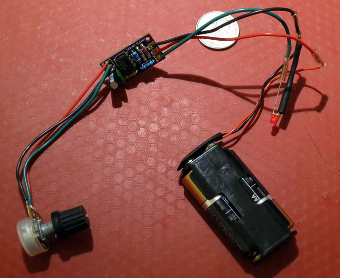
This is a simulation of the Telrad using a standard LED for testing. Yep, it blinked. In actual use I found that the circuit drained the batteries a bit quicker than the stock Telrad does.

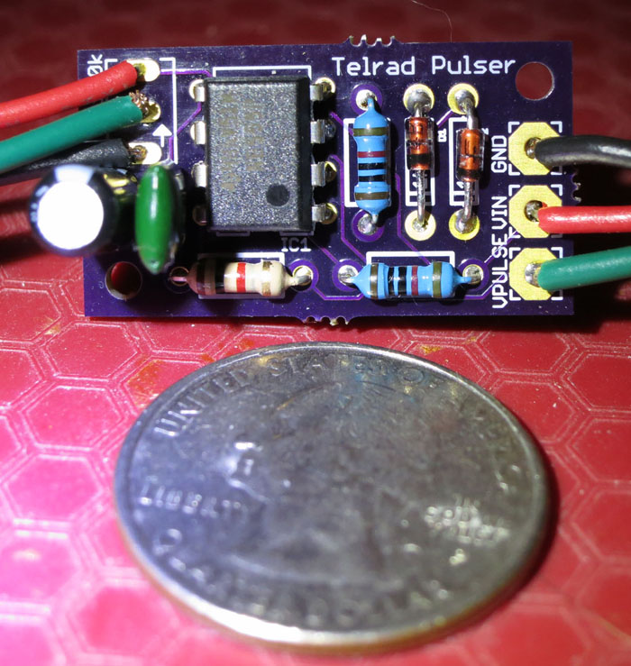
Above is the finished board with the parts installed with a U.S. quarter for size reference.
The three wires on the left (black near the cap is harder to see) go to the potentiometer. The wires on the right (from the top) are ground (GND), +3v in from the battery pack (VIN) and blinking +3v out to the Telrad reticle (VPULSE). The blue resistors are 1% tolerance instead of the usual 5% which isn't critical but more accuracy is better.

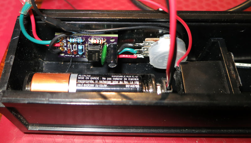
Above is the board in the Telrad. I used a small dab of GE Silicon II glue to attach it to the inside of the Telrad. The wires to the 100k potentiometer are pretty short. The foam that came with my Telrad to stop the battery holder from moving was cut in half and placed at each end of the battery pack (not in the photo). Note that the original AA battery holder was replaced with one that attaches to a v9 battery style clip. I own a few Telrads and two over the years have had broken original AA battery holders. This method allows me to quickly replace battery holders in the field, although I haven't needed to with the new holders. This is the only Telrad failure that I have experienced.

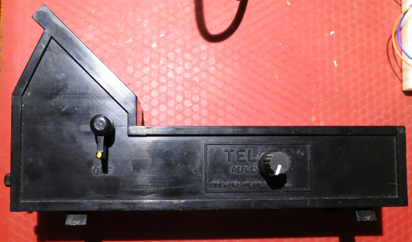
The final appearance (below) is pretty clean with only the potentiometer knob visible. I'm right handed so this arrangement works pretty well for me.
