Pulse Width Modulation (PWM) to dim a map lamp
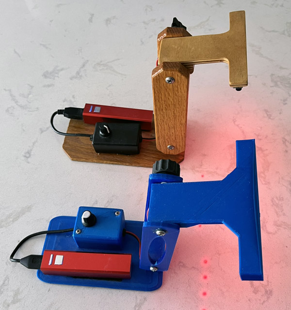
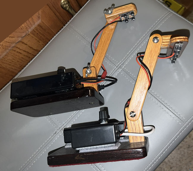
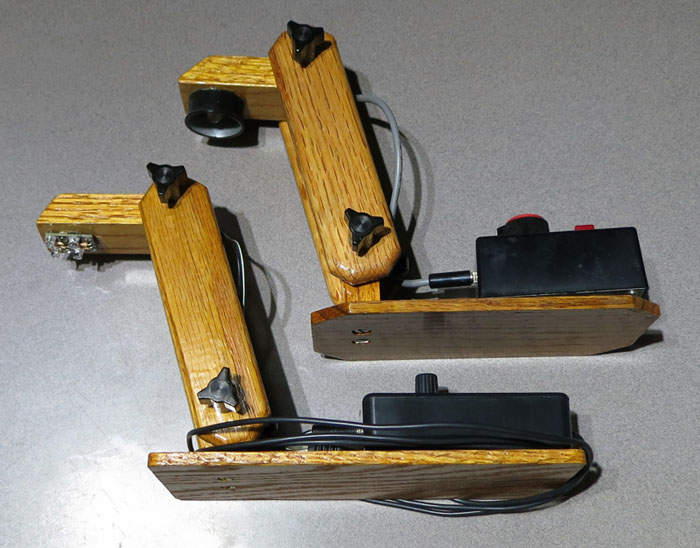
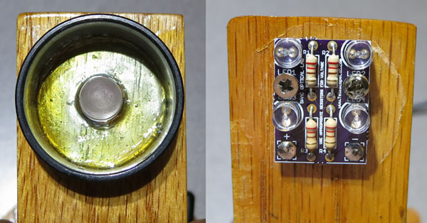
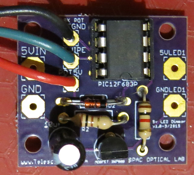
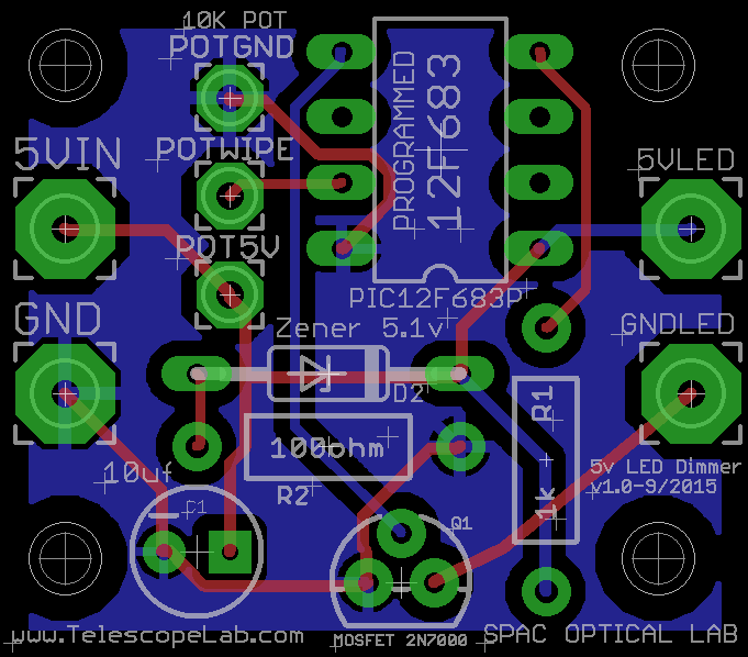
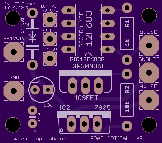
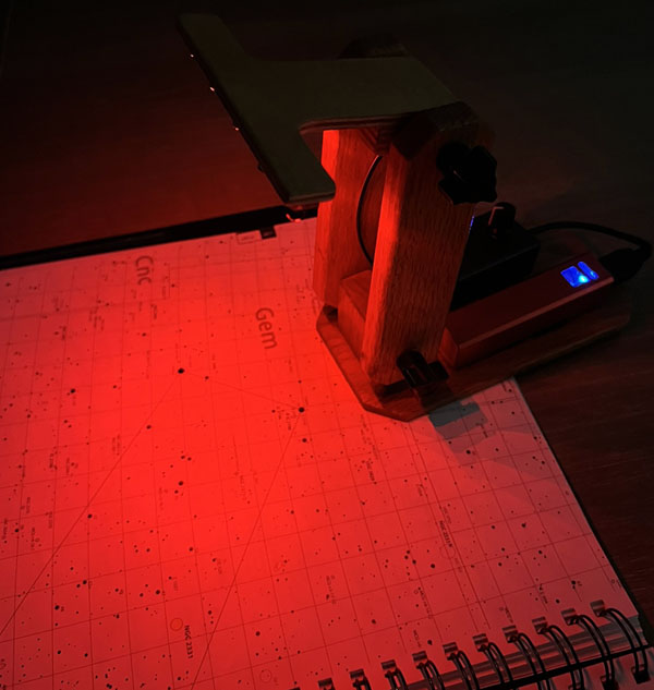
This is an update to the old LED map lamp using a wider range from dim to bright and updated LEDs with a more even and brighter light. There are two circuits, one for 4.5-5v (USB powered) and another for 9v-14v car battery connection. The LEDs are now flat top with a 1200MCD rating. I retrofitted one of the old lights to use the 5v board powering it off of a USB plug and swapping out the single LED for four brighter LEDs.
PWM divides a period of time, we'll use one second here, into equal time pieces. Just like a film your eye can't see the on and off flickering if the time frame is small, anything over around 24 frames per second. For these lights we're dividing the second into about 4000 pieces. I say about because I'm using the internal oscillator and not a quartz clock for the CPUs clock speed. Testing some of the lamps gave me a value of about 3916 Hz, pretty close to the 4000 Hz value.
Each of these 3916 time frames is then divided into 256 pieces. The 10K Potentiometer's (Pot) resistance value is converted into a value between 0 (zero) and 255 in the ADC (Analog to Digital Converter). That number is the amount of of the 255 total that the LED will be on. If it's 10% on then about 25 of the 256 total will be on and the other 90% of the time the LED will be off. If the Pot is half way on the LED will be on 128 of the 256 on, which is on 50% of the time. The percentage of time on is called the duty cycle. The larger percentage of time that the LED is on makes the light appear brighter until it becomes 100% on at its brightest.
With the LED blinking on and off at 3916 times a second your eyes see it as a brightness level, not as flickering. The big difference
between using PWM and using the direct resistance of a Pot to dim the LED is that PWM allows smoother control of the LEDs brightness. I never could find the perfect
Potentiometer value to allow from full brightness to very dim using the full range of the pot.
This project uses a PIC microcontroller and you will need to be able to download the hex code into the PIC 12F683 before it will operate. The CCS C source code is near the bottom of this page.
