Dual Channel Telescope Dew Heater Controller
Controlled by a PIC 16F88
The PIC 16F88 MUST be programmed before this project will work. The HEX file (compiled program) used to program the PIC is here. The source code is further down this page.
This is a dual channel Dew heater controller with low voltage warning (at ~ 10.5v solid on yellow LED) and lower voltage cutoff (at ~ 10v blinking yellow LED) to save your battery. A higher value would be needed to start a car. These values may be changed in the software.
The revision 2 (Rev 2) circuit being tested with a couple of dew heater strips attached.
I'm using three of the four mount points for the wires to RCA jacks. All wires carrying 12v are 14 gauge.

Above is the correct wiring for the Rev 3 and newer boards so that the pots turn clockwise to increase heat and counter-clockwise for less heat or off.
The video above shows the dew heater operation in single and dual controller mode and the low voltage warning and cutoff. The voltage cutoff was having issues when there was a load on the heaters. The solution was a brief off blink at the end of the duty cycle where all heaters are off. In the worst case that will be for 1/256th of the full cycle. During that period the voltage is checked and the yellow LEDs status is updated (solid on for warning and blinking when power is cut off to RCA jacks).
The parts that I used were from quite a few suppliers.
Source Count Item
www.oshpark.com ..... 1 .... Circuit board
www.jameco.com ...... 2 .... Red LED 655nm, 3mm, Jameco #2186603
www.jameco.com ...... 1 .... 10uf 25v Electrolytic Capacitor, #94212
www.jameco.com ...... 1 .... 0.1uf 50v ceramic capacitor, #2162581
www.jameco.com ...... 1 .... LM7805, #51262
www.jameco.com ...... 1 .... 18 pin socket, #112231
www.jameco.com ...... 8 .... 10k 5% 1/4 watt resistors, #691104
www.jameco.com ...... 1 .... straight header*, #103393
www.jameco.com ...... 1 .... jumper*, #112432
www.mouser.com ...... 1 .... RUEF400 resettable fuse, Mouser #650-RUEF400
www.mouser.com ...... 1 .... PIC 16F88 (This must be programmed to work), #579-PIC16F88-I/P
www.mouser.com ...... 1 .... 22k 1% 1/4 watt resistors, #603-MFR-25FRF52-22K
www.mouser.com ...... 1 .... 1N4001 Diode
www.sparkfun.com .... 2 .... 10K Linear Potentiometers
www.sparkfun.com .... 2 .... MOSFET FQP30N06L
www.ebay.com ........ 1 .... Water resistant project box with clear lid
www.ebay.com ........ 6 .... RCA jacks (4 to 8 - 6 fit the box nicely)
www.ebay.com ........ 2 .... Potentiometer Knobs
www.ebay.com ........ 5 .... RCA jack caps (optional to protect and plug unused RCA jacks)
www.ebay.com ........ 1 .... Yellow LED, 3mm, Super Bright (likely any super bright will work)
www.radioshack.com... 1 .... 12v auto power plug with switch and fuse

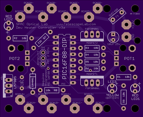
The circuit board (above) is available from OSH Park. Three of them (the minimum order) cost about $26, including shipping.
The extra holes next to RCA1D- and RCA2D- align with the mounting holes built into the project box shown on this page.
Some wiring is needed (14 or 16 gauge, I used 14) to connect the RCA jacks to the circuit board.
If you want to move the LEDs off of the board and onto the case you will need some 22 gauge wire and holders for the LEDs.
I used a Dean's power connector (from the local hobby shop) on about a foot of 14 gauge wire that connects it through the project box to the dew heater circuit board.
The Deans connector allows a safe break away point between the battery and the dew heater controller if my Dob is turned too far and pulls on the power cable.
Some very small wire ties will hold down the board end of the external pot and power wires. Use the unplated holes for this.
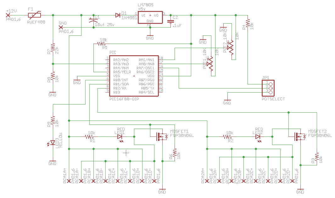
The Rev 3 Board Schematic


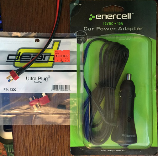
You will likely need a 12v plug to connect your battery to the dew heater. Radio Shack online carries a nice one for about $8.50, if you can locate one. It's part #270-049. I used about a foot of the 14 gauge wire to connect to the dew heater and joined it to the power cord with a Dean's Ultra plug from the local hobby shop. This gives the cord a break away point in case you turn the telescope too far and pull on the power cord.
The finished dew heater in the box with the Dean's Plug connected to a power supply (alligator clips in the upper right) for testing. I have a female Dean's Plug end on the Radio Shack 12v plug also for field use. Double check your 12v and ground when you solder the ends on. The instructions are on the Dean's package.
The box required a bit of work after the holes were drilled. The pots have an alignment pin that needs a recess to fit properly and stop them from twisting in the box. Also the grommet to protect the input power cord needed a thinner walled case. The Dremel came in handy for this. You can see the indent for the pot pin on the upper right and the thinner wall (only on the inside) on the left. The pot on the other side of the box has the indent on the opposite side of the hole near since it's flipped.
Field Power Check

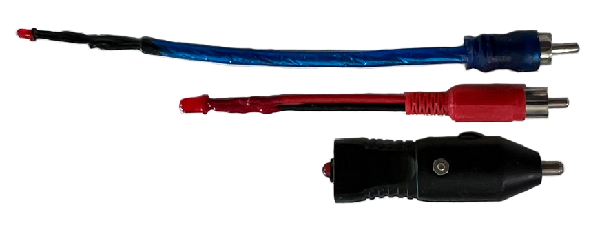
This controller has a LED for each channel that comes on when that channel gets voltage. The LED's power come from the same feed that goes out to the dew heaters so it's pretty reliable. On some dew heater controllers there is only a power on LED and not a way to see when and for how long the dew heater is getting power. Using a RCA plug, resister and LED you can plug it into the dew heater RCA jack and watch the LED blink on and off. This is particularly handy if you think that only one port on the controller has failed.
The photo shows one tester with a 3mm and 10K resistor for night testing, one with a 5mm LED and a 5K resister to test it in the daylight and one using a cigarette lighter plug to test 12v power sources. In all cases a multimeter would offer more info, like the actual voltage.
The PIC Code
I wrote the PIC code in CCS C and compiled Rev 3 under 5.047 of the CCS compiler. The code uses 27% of the PIC's ROM and 15% of the RAM. A smaller PIC could have likely been used, but I had a few 16F88's looking for a project. As I'm writing this (3/14/2017) we have eleven finished controllers and two more being built by the mirror lab crew. They are in use from the humidity of Florida to heat of New Mexico and the winters in Wyoming. So far the hardware and software has held up well and has kept the optics dry. The variable bench power supply made this project much easier.
Below is the 'Dew Heater Controller - Manual.h' code
#include <16F88.h>
#device ADC=8  // return ADC values 0-255

#fuses INTRC,NOWDT,PUT,NOBROWNOUT,NOMCLR,NOLVP
#use delay(internal=8000000)  // 8MHz

#define POT1_PIN      PIN_A0  // POT 1
#define POT2_PIN      PIN_A1  // POT 2
#define BAT_VIN_PIN   PIN_A3  // Battery in to check voltage through voltage divider
#define POT_JUMPER    PIN_A7  // connect to +5v (with a 10K resistor) to use both pots or ground for one
#define PWM_PIN       PIN_B0  // LED for low battery
#define HEATER1_PIN   PIN_B1  // MOSFET 1
#define HEATER2_PIN   PIN_B2  // MOSFET 2

#define DELAY100         100  // 1/10th of a sec
#define DELAY_LEDBLINK   500  // 1/2 second

#define POTMIN             0  // minimum return value of the ADC when reading the POT
#define POTMAX           255  // maximum return value of the ADC when reading the POT


//  the voltage divider handles 0-18.5 volts, which should be overkill for any battery
//  This scales down to 0-5v for the pic to handle (using a 27K and 10K voltage divider)
//  11v is 84.6% of 13v (full battery) so 84.6% of 255 (ADC return max) is 215.
//  This will be calculated in the program so we can enter the voltage here.
//

#define VIN_MAX           16      // Max volts allowed (should be no more than about 13v from a car battery)
#define VIN_WARN        10.5      // low volts to start the LED warning
#define VIN_CUTOFF      10.1      // low volts to start the power cutoff
#define ADC_MAX          255
#define YELLOW_LED_OFF     0      // 0 (off)  - 255 (bright)
#define YELLOW_LED_ON     25      // 0 (off)  - 255 (bright)  Use 250 for a standard brightness LED, 25 for high brightness LED

#define ONEPOT             1  // how many pots are in use - depends on POT_JUMPER value
#define TWOPOTS            2

#define FULLPULSE         92   // longer number makes for a longer total peak to peak
                              // 93 is about 3 seconds. See below for a full explanation

//#define FULLPULSE         153  // longer number makes for a longer total peak to peak
                                // 153 is about 5 seconds. See below for a full explanation


//#pragma config CCPMX = RB0 // CCP1 Pin Selection bit (CCP1 function on RB0)
#use pwm(CCP1,TIMER=2,FREQUENCY=1000,DUTY=50)

//  Approximate FULLPULSE value for full pulse seconds.
//  Each second is about 30.6 (round up or down to whole number)
//
//     SECONDS     FULLPULSE          SECONDS     FULLPULSE
//        1            31       |        6           184
//        2            61       |        7           214
//        3            92       |        8           245
//        4           122       |        9           275
//        5           153       |       10           306
//
// The interrupt (FULLPULSE) math is:
//     The timer is incremented at (CLOCK/4)/RTCC_DIV.
// The timer is incremented (8000000/4)/256 or 7812.5 times a second.
// The interrupt happens every 256 increments.
// With these numbers the interrupt happens 7812.5/256 or 30.517578125 times a second.
// Multiply that by our FULLPULSE for the actual full pulse time:
//    60/30.517578125 = once every 1.96608 us
//    1.96608 * 256 = 503 us seconds = 8.388608 seconds
//    1.96608 * 153 = 300 us seconds = 5 seconds
//    1.96608 * 62  = 121.9 us seconds = ~2 seconds


//                  PIC 16F88
//                -------------
//              -| A2       A1 |- 10k Pot #2 input
//  Battery VIN -| A3       A0 |- 10k Pot #1 input
//              -| A4       A7 |- Pot Count (+5v with 10k resistor=2, GND=1)
//        RESET -| A5/MCLR  A6 |-
//          GND -| VSS     VDD |- +5v
// PWM Batt LED -| B0       B7 |-
//     MOSFET 1 -| B1       B6 |-
//     MOSFET 2 -| B2       B5 |-
//              -| B3       B4 |-
//                -------------
Next is the 'Dew Heater Controller - Manual.c' code
/*****************************************************************

  Dew Heater Controller code for a PIC 16F88
  By Allen Maroney   http://www.allenmaroney.com
  6/4/2015

  SPAC Optical Lab   http://www.telescopelab.com

                  PIC 16F88
                -------------
              -| A2       A1 |- 10k Pot #2 input
  Battery VIN -| A3       A0 |- 10k Pot #1 input
              -| A4       A7 |- Pot Count (+5v with 10k resistor=2, GND=1)
        RESET -| A5/MCLR  A6 |-
          GND -| VSS     VDD |- +5v
PWM Batt LED -| B0       B7 |-
    MOSFET 1 -| B1       B6 |-
    MOSFET 2 -| B2       B5 |-
              -| B3       B4 |-
                -------------

*******************************************************************/

#include <Dew Heater Controller - Manual.h>

// need these to be global because they are set in main and used in the interrupt
int16 width1, width2;
int8 potreset;

// prototypes
void Read_Pot(int8 *pot1, int8 *pot2, int8 potcount);
int8 Read_BatteryVoltage(int8 adcwarnval, int8 adcoffval);


// *********************  must be before main()
#INT_RTCC
void tick_interrupt(void)
{
static int16 loop = 0, pulse1=0, pulse2=0;

if(loop++ > FULLPULSE || potreset)
  {
    loop = 0;
    potreset = 0;
    pulse1 = 0;
    pulse2 = 0;
  }

// this 'if' uses the pulse length of pot 1
// the >1 makes sure that the lowest setting turns the heater off
// at the highest setting there is a 1/250th of a pulse off blink to let you know that everything is working
if(pulse1 <= width1 && width1 > 1)
  {
    output_high(HEATER1_PIN);
    pulse1++;
  }
else
  {
    output_low(HEATER1_PIN);
  }

// this 'if' uses the pulse length of pot 2 (or the same as pulse 1 if only one pot is set up)
// the >1 makes sure that the lowest setting turns the heater off
// at the highest setting there is a 1/250th of a pulse off blink to let you know that everything is working
if(pulse2 <= width2 && width2 > 1)
  {
    output_high(HEATER2_PIN);
    pulse2++;
  }
else
  {
    output_low(HEATER2_PIN);
  }

}


void main()
{
  int8 pot1=0, pot2=0, oldpot1=0, oldpot2=0, potcount=ONEPOT;
  int8 adcwarnval=0, adcoffval=0, poweron=1;

  width1=0;  // set the default of the globals
  width2=0;
  potreset=0;

  set_tris_a(0b10001011);  // A0-A1, A3, A7 inputs; A2, A4-A5 output
  set_tris_b(0b00000000);  // B0-B7 all output

  output_low(HEATER1_PIN);
  output_low(HEATER2_PIN);
  delay_ms(DELAY100);  // let the internal R/C clock charge up and stabilize

  //   setup ADC ports for the pots on A0 and A1
  //   The Jumper connects to A2
  //   The voltage divider feeds A3
  setup_adc_ports(sAN0|sAN1|sAN3|VSS_VDD);
  setup_adc(ADC_CLOCK_INTERNAL);

  /// see if we are using one pot or two
  if(input(POT_JUMPER) )  // POT_JUMPER connected to 5v use two pots
      {    // blink each LED back and forth a few time if we are using two pots
      potcount = TWOPOTS;
      output_high(HEATER1_PIN);
      output_low(HEATER2_PIN);
      delay_ms(DELAY_LEDBLINK);
      output_low(HEATER1_PIN);
      output_high(HEATER2_PIN);
      delay_ms(DELAY_LEDBLINK);
      output_high(HEATER1_PIN);
      output_low(HEATER2_PIN);
      }
  else  // POT_JUMPER connect to GROUND (default)
      {  // blink both LEDs on for a second at the same time if we use one pot
      potcount=ONEPOT;
      output_high(HEATER1_PIN);
      output_high(HEATER2_PIN);
      delay_ms(DELAY_LEDBLINK);
      }
  delay_ms(DELAY_LEDBLINK);
  output_low(HEATER1_PIN);  // turn off the LEDS
  output_low(HEATER2_PIN);
  delay_ms(DELAY_LEDBLINK);


  // calculate the minimum threshold for the low battery LED to start lighting up
  // we only need to calculate these once
  adcwarnval = (int8)((double)(ADC_MAX-1) * ((double)VIN_WARN/(double)VIN_MAX));
  adcoffval  = (int8)((double)(ADC_MAX-1) * ((double)VIN_CUTOFF/(double)VIN_MAX));

  //// Setup CCP to PWM Mode
  setup_ccp1(CCP_PWM);
  setup_timer_2((Long int)T2_DIV_BY_16,255,1);
  set_pwm1_duty(YELLOW_LED_ON);

  // set up the interrupt
  set_rtcc(0);
  setup_counters(RTCC_INTERNAL, RTCC_DIV_256);
  enable_interrupts(INT_RTCC);
  enable_interrupts(GLOBAL);

  while(true)
  {
  poweron = Read_BatteryVoltage(adcwarnval, adcoffval);

  if( poweron )  // as long as the battery is > VIN_CUTOFF
      {
      Read_Pot(&pot1, &pot2, potcount);

      // stop jittering
    if(oldpot1 < pot1-1 || oldpot1 > pot1+1 ||
        oldpot2 < pot2-1 || oldpot2 > pot2+1 )
        {
        width1 = (int16)((float)FULLPULSE * ((float)pot1/(float)POTMAX)); // pot1 values 0-255
        width2 = (int16)((float)FULLPULSE * ((float)pot2/(float)POTMAX)); // pot2 values 0-255
        oldpot1 = pot1;
        oldpot2 = pot2;
        potreset = 1;
        }
      }
    else   // low battery turns off the mosfets
      {
      width1=0;   // turn off power to mosfet 1
      width2=0;   // turn off power to mosfet 2
      if( pot1 > 2) // forces going into the pot if() should the power go back up
            { oldpot1 = pot1-2; }
      else  { oldpot1 = pot1+2; }
      }

    delay_ms(DELAY100);    // 1/10th sec
  }

}


// ********************* START READ POT

void Read_Pot(int8 *pot1, int8 *pot2, int8 potcount)
{
  ////////////////  READ 10K POTS //////////////////
  Set_adc_channel(0);  // Select Analog port connected to pot1 (A0)
  delay_us(20);
  *pot1 = read_adc(); // Read value
    if( *pot1 < POTMIN+1 )
        { *pot1 = POTMIN+1; }
    if( *pot1 > POTMAX-1 )
        { *pot1 = POTMAX-1; }

  if( potcount == TWOPOTS )
  {
      Set_adc_channel(1); // Select Analog port connected to pot2 (A1)
      delay_us(20);
      *pot2 = read_adc(); // Read value
      if( *pot2 < POTMIN+1 )
          { *pot2 = POTMIN+1; }
      if( *pot2 > POTMAX-1 )
          { *pot2 = POTMAX-1; }
  }
  else
  {
      // pot #2 not used so return pot 1's value
      *pot2 = *pot1;
  }
}

// ********************* START READ_BATTERYVOLTAGE

int8 Read_BatteryVoltage(int8 adcwarnval, int8 adcoffval)
{
  static int8 vin=ADC_MAX;  // start with no warnings
  static int8 ledon=YELLOW_LED_ON, ledctr=0, lowvoltjitterwarn=0, lowvoltjittercutoff=0;

  ////////////////  BATTERY VOLTAGE IN //////////////////
  Set_adc_channel(3);  // Select Analog port connected to A3
  delay_us(20);

  if(!input_state(HEATER1_PIN) && !input_state(HEATER2_PIN)) // only update voltage when the heaters are off
      {
      vin = read_adc(); // Read value
      }

  // once the voltage drops to the warn or cutoff level
  // this raises the value (if>0)  to get back to the higher
  // state to reduce blinking between states.
  adcwarnval += lowvoltjitterwarn;
  adcoffval += lowvoltjittercutoff;

  if( vin > adcwarnval )
      {  // all is well, > 11V
      lowvoltjitterwarn=0;  // back to normal for warn
      lowvoltjittercutoff=0;  // back to normal for cutoff
      set_pwm1_duty(YELLOW_LED_OFF);
      return(1);  // power on to the heaters
      }
  else if( vin > adcoffval )
      {  // low power warning > 10v <= 11v turn yellow LED on solid
      lowvoltjitterwarn=1;
      lowvoltjittercutoff=0;  // back to normal for cutoff
      set_pwm1_duty(YELLOW_LED_ON);
      return(1);  // power on to the heaters
      }
  else     // <= 10v
      { // cut off power, blink yellow led
      lowvoltjittercutoff=1;
      if(ledctr++ > 5 )    // 5 = 1/2 sec blinks (10 = 1 sec blinks)
        {
        if(ledon == YELLOW_LED_ON)  // if yellow led currently on then turn it off
              { ledon=YELLOW_LED_OFF; }
        else  { ledon=YELLOW_LED_ON; }
        set_pwm1_duty(ledon);
        ledctr=0;
        }
      return(0);  // power OFF to the heaters
      }
}
Below are some of my assembly notes
Also check out this PDF of some other assembly notes including a template on where to drill the holes on the case.
This project requires that the PIC 16F88 is programmed. The PIC 16F88 is a microcontroller - basically a computer on a chip. You will need a PIC programmer (I'm using a TL866ii Plus Programmer) or locate someone who has one. There are many web sites that describe how to build a programmer and quite a few commercial versions. Another option is to contact the local robotics club or something similar on MeetUp.com and see if anyone locally will program the PIC for you. You will need a PIC 16F88 in a DIP form, which cost about $4.50 (2025 price) each plus shipping and the HEX file on a USB device.
Soldering on a silicon mat used for hot cooking pots is a great way to protect your table while soldering.
Use 200-320 grit sandpaper to slightly scratch up the TO220 parts (FQP30N06L and LM7805) and where you will solder on the RCA jacks. Even with flux this will make a much better connection. Really, do this.
Test the yellow LED by connecting the power input to a 9v battery. It should cause the yellow LED to blink on and off at about a 1/2 second cycle. The red LEDs will not come on due to low voltage.
Install the lowest profile items first, starting with the resistors. This will allow you to apply pressure on them when you flip the board over. Resistors, diode, LEDs, 18 pin socket, 3 pin jumper, MOSFETS, RUEF400 and then the external wires to the potentiometers and the power input
The clear box cover is a bit hazy on all seven of the boxed that I have purchased. If you happen to be a mirror grinder, Cerium Oxide on a wet paper towel clears up the display nicely. If not, toothpaste on your finger does almost as good (and is quite a bit cheaper).
Although not required, I recommend that you use resistors with the closest values to 22k for R8 and 10k for R7 as possible to their stated values. This is the voltage divider and more accurate resistor values here will make the 10.5v warning and 10v cutoff more accurate. If you have 1% tolerance resistors available, great. If not try metering a few of the 5% and see which is the closest.
I recommend soldering the short wires from the board to the RCA jacks on the board before screwing it in the case. Attaching these wires to the RCA jacks is one of the more difficult parts of the project. Tinning the RCA connectors first makes it easier.
The red LEDs in the parts list are 3mm diffused 655nm at 0.8mcd. The 3mm LEDs fit nicely on the board. These are a deep red standard brightness LED. If you use a different LED, like a super bright LED, then you will likely need a different resistor on R1 and R2 to dim it down. Test your LEDs with different resistor values to see what brightness if right for you at night. I tried nine different red LEDs to find what I felt was the best night vision saving combination. If you want to change the resistor values for the LEDs:
R1 controls the brightness on red LED 1 (15k=really dim; 10k=medium dim; 4.7k=can be easily seen in a well lit room)
R2 controls the brightness on red LED 2 same as above
R9 partially controls the brightness on the yellow battery warning LED A 10K resistor should be okay for most needs and make the specified yellow LED medium dim.
The yellow LED is diffused super bright (no other specs available) 3mm if placed on the board. The PIC handles dimming it with Pulse Width Modulation (PWM at 482Hz) although the r9 resistor limits the maximum brightness. The yellow LED toggles off with a duty cycle of 0 (zero) and on with a duty cycle of 10% (1/10th of full visual brightness).
After years of use
I've been using three of these dew heater controllers on my Dobs now for more than 5 years. They work well. The only issue that I had was a bad solder joint on one of the MOSFETs caused one of the channels to stop working and I put everything on the other side. My mistake. The solder issue was fixed the next day. It also helpled a friend identify that they had a bad battery that wasn't fully charging.
Some of these boards were also the first time the bulder ever soldered. We had someone with more experience helping them and it was a pleasure to see how happy that they were to make something that they will actually use. One board that failed to power up one side of heaters was traced back to a manufacturing defect where one of the bottom traces had a gap. After locating the issue we soldered a short jumper wire and all was well. The builder, a teenager, was able to understand a basic schematic and trouble-shoot the issue when we were finished.
Astronomy really is one of the only sciences where an average person really can make everything that they need, although I haven't tried making an eyepiece yet.
The Future
While I left room for adding features I like the simplicity of the heater as it is. If you want more features, like checking the dew point, there are some fine commercial offerings out there. That's about all that I can think of at the moment.
