The Original Robo Foucault Tester
See the USB Robo v2 for new builds
The robotic Foucault Tester was the brain child of James Lerch.
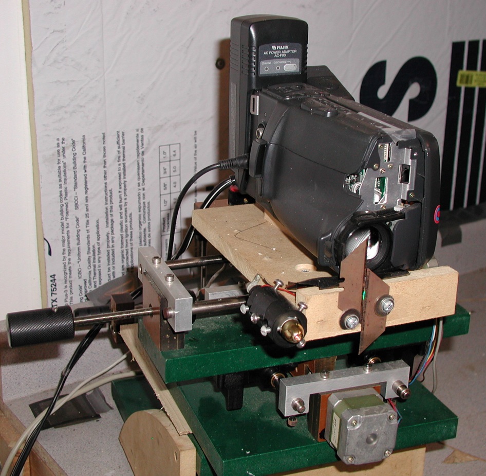
This is the well used and abused robo foucault camera set-up that we used at the mirror lab for a dozen years. After the camera died it was replaced with an even larger mid-80's full size VHS camera using the same stand. This was in use for another eight-plus years at the mirror lab and since 2019 it has been set up at one of our lab instructor's house who is still testing mirrors with it. The VHS camera, shown further down, was removed from the new stand before that was finished to keep the tester going.
If you are considering building a robo Foucault tester see the USB version link at the top of this page to avoid needing a parallel port motor controller.
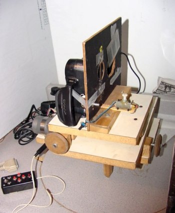
The previous photo is actually the second robo foucault camera stand. The prototype, above, needed some changes to be able to hold up to the mirror lab's use..
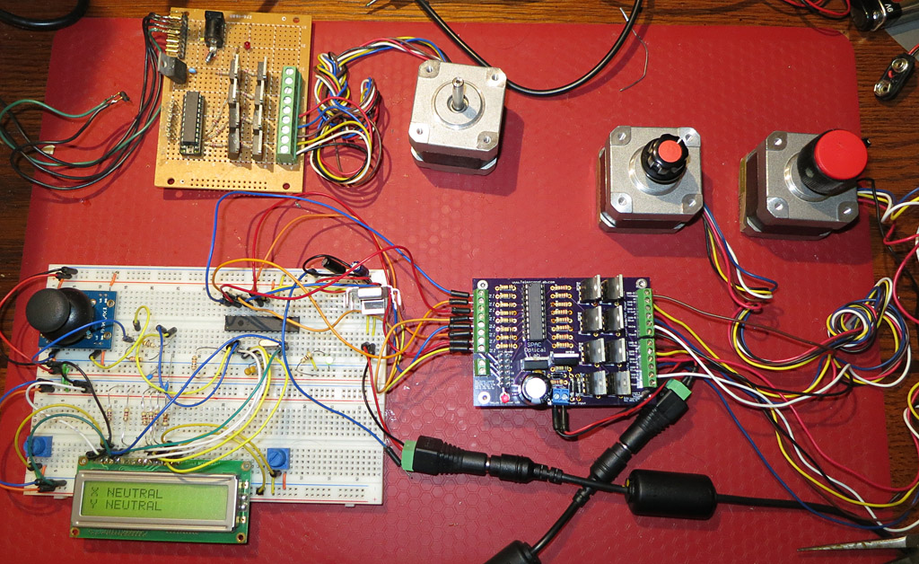
My prototype of James' stepper circuit (top) with a single stepper motor attached worked well enough. The purpleish circuit board created in Eagle PCB software and fabricated by OSH Park. The first version of this board (without the 7805) been running the robo Foucault tester at the mirror lab for the past three months. The white test circuit for the stepper controller and it uses PIC 18F2550 (the long black IC) for the brains to read a small joystick (upper left on the board) and control the two steppers with three speeds in each direction and neutral (stopped) in the center position. In the fastest mode full stepping is used for speed. The LCD display is mostly for debugging.
The first version of the controller is in the photo below mounted in an external Sun hard drive case, although almost any external hard drive case will work. This is the one in use. The parallel cable from the computer comes in on the top right and the output to the motors is through the DB9 on the top left. The thicker yellow (+12v), black (ground) and red (+5v) wires are from the hard drive power supply. Newer versions of the circuit only need around 12v and ground, which make it easier to use with a car battery.
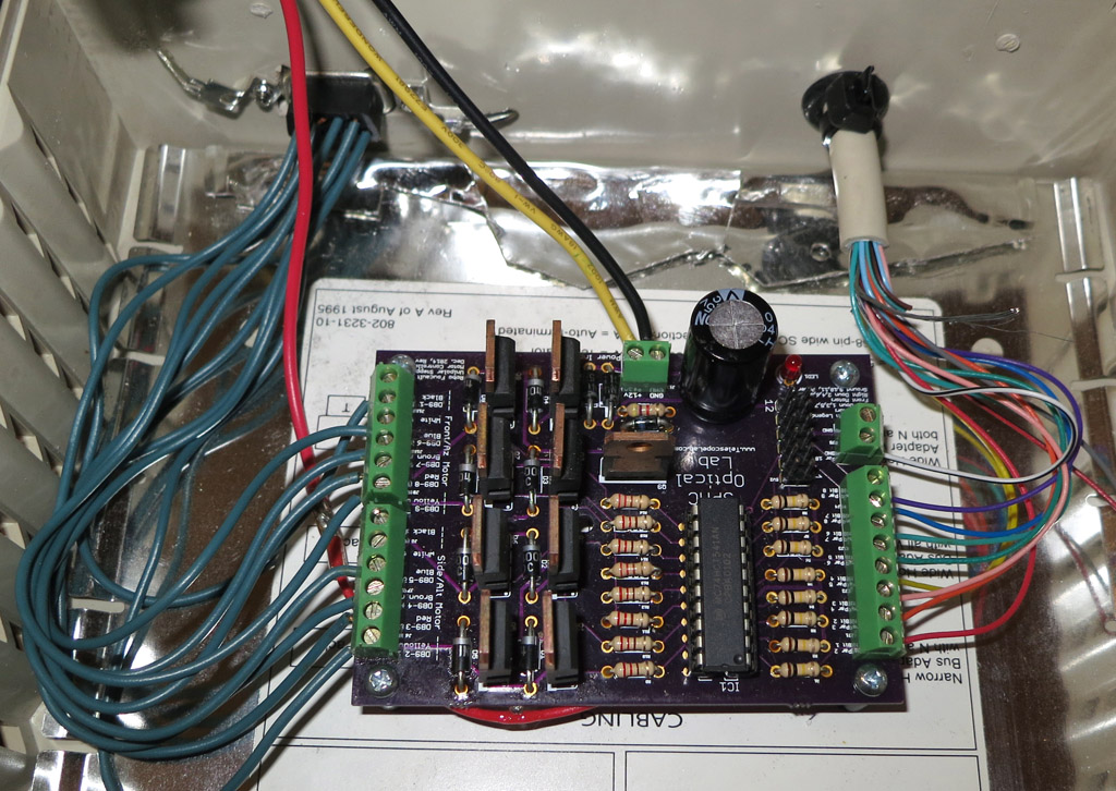
If you're not into stepper circuits this one is easy. There are eight wires from the parallel port going into it and eight control wires going out to the stepper motor (four for each stepper plus 12v power). When the PC sends a 5v signal over one of the control wires (ON) the controller board allows 12v to flow on the matching wire to the stepper. The board is really a fast, digital ON/OFF switch that handles eight inputs independently. The third and, hopefully, final version of the board are now available at OSH Park. The only changes are on the silk screen to clear up some connections. The link to order the board is available from OSHPark Circuit Boards
OSH Park requires that you order a minimum of three boards for $36.85 for three (as of 5/2015), including shipping. I could have made the board a bit smaller but I wanted to make it easy to solder with reasonable spaces between solder locations, no surface mounted parts and enough info on the silk screen to make sense.
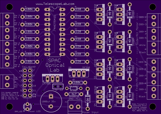
The board's actual size is 3.22x2.29 inches (81.89x58.09 mm). The terminal blocks are the smaller size
using a 3.5mm pitch that the usual size. Here's a parts list (you still need two motors (Jameco #155433) for the platform, video capture,
appropriate camera and a Windows (XP and Vista tested) computer with a parallel port):
1 Robo Parallel Port Stepper Controller Circuit Board
1 20 pin soldertail socket
1 78HCT541 (or SN74HCT541N)
12 Terminal Blocks, Dual 3.5mm pitch (may omit is soldering wires to board)
9 100k 1/4 watt resistors
8 220ohm 1/4 watt resistors
1 4.7k resistor
9 IRF540 MOSFET
1 33v Zener diode
9 1N4001 Diodes
1 LM7805 5v voltage regulator
1 1000uF 35v electrolytic capacitor
1 0.1uF ceramic capacitor
1 Red LED, 3mm
1 2x6 straight header (only needed if using external control board)
1 Power supply, 12v at least 1.5A (1A is right at the limit SUGGEST 1.5a+)
1 Parallel port cable to connect the computer to the board.
1 An appropriate project box (An external hard drive case with built in power supply may work - check amp output)
At the lab the board's output goes to a DB9 socket (labeled on the board) and a old serial cable is used to connect that to the motors. More on the wiring is here. As long as the correct motor wire goes to the correct board output the connectors are up to you.
The two rows of header pins below the LED (next to the big Cap) allows an alternative connection to another system with he ability to control all eight outputs. Additionally, it feeds back 12v, 5v (add a heat sink to the 7805 if you do this) and ground. This should make it easier to connect a smart board, like the one with the joystick, to manage the stepper controller. If you are connecting the board to the parallel port as the controlling system the control header and Terminal block J5 are not needed.
The 74HCT541 chip is getting a bit harder to locate. As of March 2015 Mouser.com has a few thousand to sell. I have tested the SN74HCT541N as a direct replacement and it appears to work well. Use whichever is easier to locate.
If you build this do yourself a favor and use some fine sandpaper on the pins of the IRF540s and the LM7805 before soldering. I struggled getting the solder to stick to both - and I used a good no-wash flux - before I lightly sanded the pin surfaces.
I started to make a new robo Foucault stand using precision drawer sliders and later decided that a better solution was to change the software to use a more modern motor controller and a modern, smaller camera. See the USB Robo v2 page for information about that.
The first level of the platform that controls distance to the mirror.
The second level that controls cutting the knife edge in and out (side to side).
The final level holds the camera, knife, alignment laser and LED. All controls were placed to match the Lab's Robo. The first level uses a 1/4" x 20 tpi rod and the second level uses a 1/4" x 28 tpi rod, again, matching the Lab's Robo. The overall size is bigger than what is at the lab. Partially because the drawer sliders are bigger and partially because I'm using a old, huge full-size VHS camera that has been in my closet for years.
Here's the rough to-do list:
- create a real circuit board that others could use to build their own Robo Foucault.- DONE, but not published yet
- Connect the stepper controller circuit to a DB25 cable (connects to the PC) and to the stepper motors with a longer cable (ideally match the existing robo's wiring) - DONE
- Round the corners and urethane the plywood - DONE
- Attach the threaded rod to the level above each rod (maybe add bigger knobs)
- Attach the drawer sliders to the appropriate levels and attach each level to the lower level's threaded rod nut
- Add a Knife, alignment laser and LED with dimmer to level 3
- Add front feet - Done
- Attach the camera to level 3
